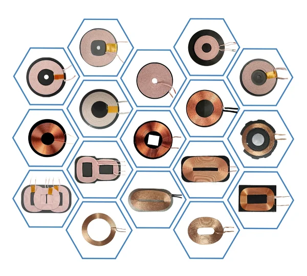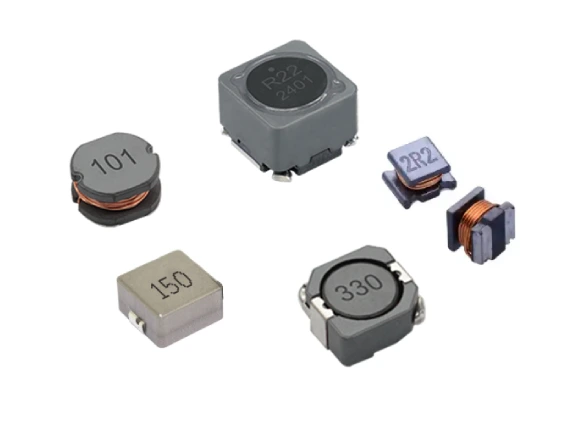
SMD inductors, full name surface mount device inductors, refer to inductors made using printed circuit manufacturing technology, directly mounted on the surface of the circuit board, and connected to other components through pins. SMD inductors usually consist of a magnetic core and a shell. The magnetic core is wound with a winding of highly conductive wire, which produces an inductive effect on signals of a specific frequency. SMD inductors come in a variety of packaging forms, including small packages, high-power packages, etc. Choosing the right package can improve installation efficiency and circuit performance.
(★ If you want to know more information, you can refer to the following article: •The Difference Between Shielded Inductors and Unshielded Inductors | Zxcompo Inductor Factory)
In electronic circuit design, SMD inductors often play a vital role in ensuring optimal performance. Yet, many engineers and hobbyists overlook their importance, resulting in inefficient designs. In this article, we’ll uncover 10 essential facts about SMD inductors that will elevate your understanding and help you make better choices for your projects.
1. What Are SMD Inductors?
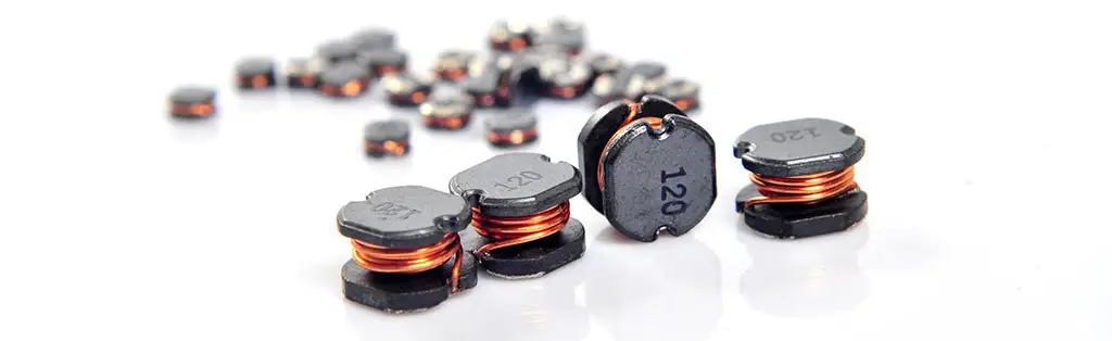
Surface-Mount Device (SMD) inductors are compact electronic components designed to store energy in the form of a magnetic field. They are widely used in power supplies, filters, and RF circuits due to their small size and reliability.
2. Why Size Matters
Size directly impacts the current handling and inductance value. Smaller inductors may save board space but might compromise efficiency. Choosing the right balance is key.
3. Material Composition
The core material, typically made of ferrite or powdered iron, significantly affects the frequency range and loss characteristics of the inductor. Different materials suit different applications.
4. Key Applications
SMD inductors are indispensable in DC-DC converters, RF amplifiers, and EMI noise suppression. Knowing where and how to use them can drastically improve your circuit’s performance.
5. Inductance Value Accuracy
Pay attention to the inductance value. A mismatch with your circuit requirements can lead to inefficient power delivery or frequency issues.
6. Current Ratings
Select SMD inductors with an appropriate current rating to avoid overheating or malfunction. Underestimating this parameter can damage your circuit.
7. Q Factor Matters
The Quality Factor (Q factor) measures the efficiency of the inductor. Higher Q values mean lower losses and better performance in high-frequency applications.
8. Frequency Range
Different SMD inductors are designed for specific frequency ranges. Picking the wrong inductor can lead to poor signal clarity or reduced efficiency.
9. Temperature Considerations
Temperature greatly affects an inductor’s performance. Ensure the inductor you choose can withstand the operating temperature range of your design.
10. Cost vs. Performance
While it’s tempting to opt for cheaper components, investing in high-quality SMD inductors can save you troubleshooting efforts and ensure stable, long-term performance.
We can also combine engineering selection, design and application considerations to understand the 10 key points that SMD inductors must have to achieve maximum efficiency:
🔧 1. Prioritize multi-layer/integrated molding structure
Multilayer inductors (such as the WE-MI series) shield external interference through ferrite cores and reduce crosstalk, which is suitable for high-density filtering and resonant circuits; integrated molding inductors (molded inductors) have smaller leakage inductance, higher efficiency, and excellent EMI shielding effect, which is suitable for high current scenarios.
⚡ 2. Saturation current must be higher than the peak operating current
Saturation current is defined as the critical value when the zero current inductance value drops by 30%. If the operating current exceeds the saturation current (ISAT), the inductance value will drop sharply, resulting in a decrease in efficiency, and at least 20% margin must be retained.
🔌 3. DC resistance directly affects loss
Excessive DC resistance (DCR) will cause copper loss heating and reduce conversion efficiency. In low-voltage systems, ultra-low DC resistance (DCR) models (such as the power multilayer inductor WE-PMI series) must be selected, and wide copper foil PCB wiring must be used to reduce impedance.
📡 4. The self-resonant frequency must be much higher than the operating frequency
The impedance of the inductor changes sharply near the self-resonant frequency (SRF), thereby losing the energy storage function. The switching power supply must ensure that SRF>2 times the switching frequency (for example, for 4MHz applications, SRF>8MHz).
🌡️ 5. Temperature management determines long-term reliability
Rated current is limited by temperature rise, and heat dissipation needs to be optimized in high current scenarios:
Copper foil + via array is used for heat dissipation at the bottom of the inductor
Independent power and ground wire design to avoid thermal coupling
Ni-Zn magnetic cores are used for high temperature environments (support ≤150℃).
🔄 6. Pay attention to the balance of iron loss and copper loss in high-frequency applications
Iron loss: eddy current/hysteresis loss of the magnetic core (increases with increasing frequency)
Copper loss: skin effect/proximity effect of the winding (increases with increasing frequency)
Optimization strategy: >1MHz uses metal alloy magnetic powder cores (such as sendust magnetic powder), <1MHz uses ferrite magnetic powder cores.
💾 7. Minimization principle of power circuit layout
Input capacitor → switch tube → inductor → output capacitor to form a compact circuit.
The switch node wiring should be ≤5mm to avoid radiated noise.
The feedback signal should be away from the power path and shielded with a ground wire.
🧩 8. The trade-off between miniaturization and high performance
Power stacked inductors (such as 1008 packages) are recommended for portable devices. Its volume is 90% smaller than that of wound inductors, but the following points need to be weighed:
Higher switching frequency (4~10MHz) can reduce size, but increase iron loss.
Material with high magnetic permeability can reduce volume, but the saturation current will be reduced.
🛡️ 9. Structural selection affects EMI performance
Shielded inductors (such as molded/integrated inductors) have radiated noise that is more than 20dB lower than unshielded inductors, making them the first choice for sensitive circuits.
⚠️ 10. Avoid self-resonance and harmonic interference
It is forbidden to operate near the self-resonant resonant frequency (SRF), and check the circuit harmonics:
Add RC filters to suppress switch node ringing
Parallel ceramic capacitors (100nF) can absorb high-frequency glitches.
Design tips: “Leave margin for saturation current, low DCR is the key; avoid SRF high frequency, if heat dissipation is poor, efficiency will be reduced; select core materials according to frequency, shielded structure noise is lower.”
Conclusion:
SMD inductors may seem insignificant, but their impact on electronic systems is significant. Knowing these 10 key factors will allow you to choose the best inductor for your needs and ensure maximum efficiency for your design.
In the competitive electronic component market, Zxcompo’s SMD power inductors stand out for their high performance, reliability, and global support network. If you are looking for a reliable inductor solution, consider Zxcompo to take your design project to the next level. Simply contact us for a sample: sales@ZXcompo.com.
Take action now! Visit Zxcompo’s official website to explore more product specifications and application cases, and you will find that choosing Zxcompo is an investment you will never regret. Zxcompo will help you succeed!