In this article, we will discuss the five main aspects of surface mount power inductor failures in practical applications, including solderability, wettability, poor soldering, open circuits, and core damage. But before we delve into these failure causes, let’s understand the failure modes of inductors and the mechanisms behind surface mount inductor failures.
Failure Modes of Inductors: Inductor value and other performance parameters may degrade, leading to open circuits or short circuits.
Surface Mount Power Inductor Failure Causes:
a. Mechanical Stress During Core Processing: Excessive mechanical stress during the core manufacturing process that is not adequately released.
b. Impurities or Voids in the Core Material: Presence of impurities or voids in the core material, causing non-uniformity and affecting the magnetic field characteristics, resulting in a deviation of the core’s permeability.
c. Sintering-Related Cracks: Cracks formed due to sintering after the manufacturing process.
d. Solder Splattering During Copper Wire-to-Pad Soldering: During the soldering of copper wires to pads, splattering solder may come into contact with the insulation layer of the coil, causing short circuits.
e. Thin Copper Wire Resulting in False Soldering: Thin copper wires can lead to false soldering when connecting to copper pads, causing open circuit failures.
(★If you want to know more about power inductors, you can refer to the following article: •Why Are Power Inductors So Important In Power Supplies And Electronics?)
1. Solderability
For low-frequency surface mount power inductors, the inductance may increase by less than 20% after reflow soldering.Soldering temperatures during reflow soldering may exceed the Curie temperature of the low-frequency surface mount inductor material, resulting in demagnetization. After demagnetization, the permeability of the surface mount inductor material returns to its maximum value, causing an increase in inductance. Typically, the control range required is that the inductance of the surface mount inductor should increase by less than 20% after solderability testing.
Solderability issues can sometimes arise when hand-soldering small batches of circuits, with all circuits performing within specifications (as the surface mount inductor may not be uniformly heated, causing minimal inductance increase). However, in large-scale surface mount processes, it may be noticed that some circuit performance degrades. This could be attributed to the increased inductance of surface mount inductors after reflow soldering, affecting the circuit’s performance. Areas with stringent requirements for inductance accuracy (e.g., signal reception and transmission circuits) should pay greater attention to solderability of surface mount inductors.
Testing Method:Measure the inductance value of the surface mount inductor at room temperature and then immerse it in a molten solder pot for approximately 10 seconds. After the surface mount inductor has completely cooled, measure its new inductance value. The percentage increase in inductance represents the solderability of the surface mount inductor.
2. Wettability
When reaching reflow soldering temperatures, silver (Ag) reacts with tin (Sn) to form a eutectic alloy. Therefore, tin plating cannot be directly applied to the silver terminations of the surface mount inductor. Instead, nickel plating (approximately 2 µm) is applied to the silver terminations to form an isolation layer before tin plating (4-8 µm) is applied.
2.1Wettability Testing
Clean the terminations of the surface mount inductor to be tested with alcohol and then immerse it in a molten solder pot for approximately 4 seconds. If the solder coverage on the terminations of the surface mount inductor exceeds 90%, it passes the wettability test.
2.2 Common Wettability Issues
2.2.1. Termination Oxidation
Prolonged exposure to high temperatures, humidity, chemicals, or oxidative gases (such as SO2, NO2) or extended storage times can cause oxidation of the tin (Sn) on the surface mount inductor terminations, resulting in SnO2 formation and decreased wettability.
2.2.2. Thin Nickel Plating
Inadequate nickel plating thickness may not provide proper isolation. During reflow soldering, the tin (Sn) on the surface mount inductor terminations first reacts with its own silver (Ag), affecting the solder paste’s co-melting with the tin on the terminations, leading to silver leaching and reduced wettability.
Detection Method: Immerse the surface mount inductor in a molten solder pot for a few seconds and then inspect the terminations for any pitting or exposure of the ceramic body, indicating silver leaching.
2.2.3. Poor Soldering
Internal Stress – If significant internal stress is generated during the manufacturing process of the surface mount inductor and is not adequately relieved, surface-mounted inductors may exhibit “tombstoning” effects during reflow soldering.

In determining whether surface mount inductors exhibit significant internal stress, a relatively straightforward method can be employed:
Take several hundred surface mount inductors and place them in a standard oven or low-temperature furnace. Gradually raise the temperature to approximately 230°C (446°F) and maintain this temperature. Observe the conditions inside the furnace. If you hear crackling or popping sounds, or even witness components jumping, it indicates that the products possess significant internal stress.
Component Deformation:If surface mount inductor products exhibit bending or deformation, this can lead to an amplification effect during soldering.
Poor Soldering and Cold Solder Joints: Soldering should ideally exhibit the pattern as shown in the diagram below.
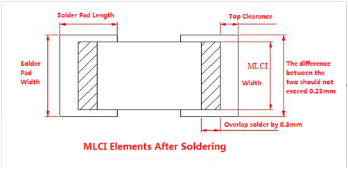
Improper solder pad design can lead to various issues when working with surface mount inductors. Here are some key considerations to ensure proper solder pad design:
a. Symmetrical Solder Pads: Solder pads at both ends should be symmetrically designed to avoid size discrepancies. Otherwise, different melting times and wetting capabilities may occur at each end.
b. Solder Length:The length of soldering, i.e., the overlap length between the metal terminations of the surface mount inductor and the solder pad, should be at least 0.3mm.
c. Solder Pad Clearance:The clearance length of solder pads should be kept minimal, generally not exceeding 0.5mm.
d. Solder Pad Width:The width of the solder pads themselves should not be excessively wide. The reasonable width compared to MLCI (Metal Layer Chip Inductor) width should not exceed 0.25mm.
Misalignment due to Uneven Solder Pads or Solder Paste Movement: Surface mount inductors may experience misalignment, causing an angular shift (θ angle). This angular shift can result from the wetting force generated during solder pad melting and may manifest in three main scenarios. Self-correction is the most common, but occasionally, a steeper pull angle or single-point correction can occur. This can lead to surface mount inductors being pulled towards one solder pad, or even lifted, causing them to tilt or stand upright (referred to as “tombstoning”). Modern surface mount machines equipped with angle-offset visual inspection can reduce the occurrence of such failures.
Soldering Temperature: The temperature profile of a reflow soldering machine must be set according to the solder material’s requirements. It should aim to ensure that the solder at both ends of the surface mount inductor melts simultaneously. This prevents discrepancies in wetting force times, which can lead to component displacement during soldering. If soldering defects occur, it is essential to check whether the reflow soldering machine’s temperature settings are abnormal or if there have been changes in solder material.
3.Temperature-Induced Damage
Surface mount inductors are susceptible to damage under rapid cooling, rapid heating, or localized heating conditions. Therefore, precise control of soldering temperature is essential during assembly, and the contact time during soldering should be minimized.
3.1 Open Circuits on Assembly
Surface mount inductors may experience poor soldering, solder joint defects, or other issues leading to open circuits when mounted on the circuit board. It is advisable to test surface mount inductors after removal from the circuit board to assess their performance and detect any issues.
3.2 Current Breakdown
Selecting surface mount inductors with lower rated currents or the presence of high transient currents in the circuit can lead to a current breakdown. This can result in surface mount inductor or ferrite bead failure, leading to open-circuit conditions in the circuit. Surface mount inductors exhibiting signs of current breakdown may show evidence of burning. When a current breakdown occurs, the number of defective products is typically higher, with failure rates exceeding a hundred per batch.
3.3 Soldering-Related Opens
During reflow soldering, rapid cooling and heating can induce stress in surface mount inductors, enlarging defects in components with latent open circuit risks. This can lead to open circuits in surface mount inductors. Surface mount inductors should be tested after removal from the circuit board to identify any open circuits. If soldering-related opens occur, the number of defective products is usually limited, with failure rates typically less than a thousand per batch.
4. Magnetic Core Damage
Surface mount inductors may suffer from magnetic core damage due to inadequate sintering or other factors. This can result in insufficient overall strength and increased brittleness. Damage to the ceramic body can occur during surface mounting or when subjected to external mechanical forces.
4.1 Adhesion Issues
Weak adhesion of the silver layer on the surface mount inductor’s terminal ends can lead to separation or detachment during rapid heating and cooling in reflow soldering. Thermal expansion and contraction stress, as well as external mechanical impact on the ceramic body, can contribute to terminal separation or detachment. Alternatively, if the solder pad is too large, wetting force during reflow soldering may exceed terminal adhesion, causing terminal damage.
4.2 Overheating or Firing of Surface Mount Inductors
Overheating or firing of surface mount inductors may occur due to excessive soldering temperatures or the presence of microcracks during the manufacturing process. Rapid cooling and heating during reflow soldering can induce stress in surface mount inductors, leading to crystalline cracking or the expansion of microcracks, resulting in magnetic core damage and other issues.
Proper attention to these factors, from solder pad design to temperature control during assembly, is crucial for ensuring the reliability and performance of surface mount inductors in electronic circuits.
ZXcompo is a manufacturing company specializing in custom inductors, capacitors, resistors, and more. Find high-quality passive electronic components for your projects. If you have product needs and inquiries. Please contact us now: sales@ZXcompo.com