In modern electronic design, minimizing power supply noise remains a persistent challenge for engineers. Whether in smartphones, servers, or medical devices, a stable, efficient, and low-noise power supply is critical to ensuring optimal device performance. So, why is the “3-pin inductor” an ideal choice for low-noise power supply designs? Next, we will uncover its secrets and share practical application scenarios and design techniques with you.
3-Pin Inductor: From Principle to Advantages
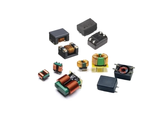
A 3-pin inductor, also known as a multi-pin shielded inductor, improves interference immunity by adding an extra ground terminal. Traditional inductors may generate electrical noise due to magnetic field interference during operation, while the structural design of a 3-pin inductor can reduce this magnetic field leakage and coupling noise. Consequently, it serves as an invaluable asset in the design of low-noise power supplies.
Furthermore, thanks to its extra ground pin, the 3-pin inductor excels particularly in addressing Electromagnetic Interference (EMI) issues. This not only reduces the power supply design’s sensitivity to external interference but also effectively reduces signal crosstalk between circuits, thereby significantly improving the stability of the device.
Leveraging its unique characteristic of “allowing differential-mode signals to pass while blocking common-mode signals,” the 3-pin inductor is widely employed in low-noise power supply designs to suppress common-mode interference and enhance power supply purity; it is particularly well-suited for applications with stringent requirements regarding EMI (Electromagnetic Interference) and SNR (Signal-to-Noise Ratio). Based on currently available information, its typical application scenarios include:
Key Applications of 3-Pin Inductors in Low-Noise Power Supplies
Leveraging its unique characteristic of “allowing differential-mode signals to pass while blocking common-mode signals,” the 3-pin inductor is widely employed in low-noise power supply designs to suppress common-mode interference and enhance power supply purity; it is particularly well-suited for applications with stringent requirements regarding EMI (Electromagnetic Interference) and SNR (Signal-to-Noise Ratio). Based on currently available information, its typical application scenarios include:
Medical Electronic Devices
Devices such as portable ECG monitors and blood glucose meters require extremely low power supply ripple (e.g., <50 μVpp) and must pose no risk of leakage current. 3-pin inductors can serve as a substitute for Y-capacitors, thereby meeting medical safety standards such as IEC 60601.
High-precision ADC/DAC power supply
In data acquisition systems, high-frequency noise from the switching power supply can directly cause sampling errors. Utilizing a 3-terminal inductor in conjunction with a π-filter (comprising input and output capacitors) allows ripple to be reduced to the microvolt level.
RF and Wireless Communication Modules
3-pin inductors are utilized in devices such as millimeter-wave radar, Wi-Fi, and Bluetooth—specifically at the pre-stage of LDOs or the input of DC-DC converters—to suppress the coupling of switching noise into sensitive RF paths, thereby preventing a degradation in sensitivity.
Automotive Electronic Systems
Applications such as ADAS domain controllers and power supplies for CAN/LIN transceivers are required to comply with the CISPR 25 Class 5 standard. 3-pin inductors provide >20 dB of common-mode suppression within the 30 MHz–100 MHz frequency range; their compact size makes them suitable for high-density PCBs.
Industrial PLCs and Sensor Nodes
In noisy industrial environments, 3-pin inductors are used to isolate digital switching power supplies from analog front-ends, preventing ground bounce and common-mode noise from interfering with signal integrity.
High-End Audio Amplifiers
3-pin inductors are used to reduce background noise and “power supply hum,” thereby enhancing the audio signal-to-noise ratio; they are particularly well-suited for applications such as microphone preamplifiers and audio codecs.
How to Optimize the Use of 3-Pin Inductors
When utilizing 3-pin inductors, designers can further optimize their performance by employing the following techniques:
– Ensure that the ground pin is securely connected to the ground plane within the PCB layout.
– Select a 3-pin inductor that is appropriately matched to the specific power requirements of the application, thereby avoiding overload or impedance mismatch.
– Carefully adjust the layout to minimize electromagnetic interference sources near the inductor.
Typical Circuit Placement
1. DC-DC Converter Input: Filters out external noise originating from the battery or power adapter.
2. Stage Preceding the LDO: Compensates for the LDO’s insufficient Power Supply Rejection Ratio (PSRR) in the high-frequency range (>1 MHz), thereby further purifying the power supply.
3. AFE (Analog Front-End) Power Supply Path: Directly provides a “clean” power supply to sensitive components such as ADCs and sensors.
Overview of Key Advantages of 3-Pin Inductors
– No Y-Capacitors Required: Eliminates the risk of leakage current, making it an ideal choice for medical and isolated systems.
– PCB Space Savings: A single component replaces the traditional “inductor + capacitor” combination, saving over 30% of board space.
– Broadband Common-Mode Rejection: Achieves 20–45 dB of attenuation across the frequency range of 1 MHz to 100 MHz.
– Supports High Switching Frequencies: Suitable for MHz-class DC-DC designs driven by GaN or SiC devices.
In the realm of low-noise power supply design, selecting the right components is half the battle—and the 3-pin inductor is a solution well worth exploring. Through thoughtful design and optimization, it can help you build a more stable and efficient low-noise power supply system.